Laser Thickness Gauge Development
 We have spent most of the last year developing our next product, which will be a laser triangulation based thickness gauge. Final testing is currently underway, and the forthcoming laser gauge is close to becoming a reality. The C-frame air gap will be 12.2” (310 mm.), and the system will be able to measure virtually any material with a thickness ranging from .040 to .750” (1 to 19 mm.).
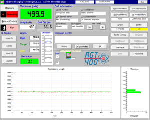
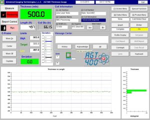
Here are a couple screen shots showing how low the electronic noise is using this new technology. The foreground image shows a .500” steel sample being measured with a 20 µ second sampling rate. The background picture shows how solid the reading becomes when we slow down the sampling rate to one millisecond-which is still ten times faster than our fastest setting today.

If you would like to receive additional information, or a budgetary proposal for our new laser thickness gauge, please let us know.
AGT400 Software Version 3.36
At Advanced Gauging we strive to continuously improve all aspects of our products, and occasionally, this includes software updates at no charge. Below are a few of the changes made in v3.36. As with most updates, many things are improved behind the scene and won’t be obvious.
Added the ability to export shift reports to Microsoft Excel in Offline Data Analysis.
[fancy_numbers variation=”teal”]
- Included a remote support client allowing us to help diagnose problems and assist software setups remotely.
- New version allows for full resizing of the main screen to any screen resolution.
- Designed for 1280 X 1024 screen resolution to take advantage of higher resolution video monitors. This results in cleaner, crisper viewing.
- Larger screen allows for design changes on main screen. More features, including quick access buttons, have been added as a result.
- Moved sub-menus to their own windows allowing them to be moved around the screen.
- Incorporated internal code enhancements to reduce CPU load.
- Updated various screen tooltips for both English and Spanish languages.
- Implemented several other minor program and functionality enhancements.
- Included framework changes to accommodate upcoming laser gauge technology.
[/fancy_numbers]
This new release will be installed for all customers during your normal semi-annual visits from June through November. We have thoroughly tested this new software and believe it to be completely reliable and bug free. However, if you find any errors, please let us know so that we may correct them. Enjoy!
ISOcheck™ vs. ISOcal™
We get this question from time to time: “How often should I do an ISOcheck™?” or “Should I ever do an ISOcal™?” To answer these questions we first need to define what happens when an ISOcheck™ and ISOcal™ are performed. The ISOcheck™ zeroes the AIR measurement (or shutter open with no material) and then checks the calibration curve using the samples inside the source head. As the name suggests, the ISOcal™ uses the internal samples to recalculate the thickness algorithm or “curve”.
In the case of an ISOcheck™, it is recommended in the AGT400 System Manual, Operation section K, to perform an ISOcheck™ once per week. AIR measurements (no material) can fluctuate for a variety of reasons. Weekly ISOchecks™ will keep the AGT400 zeroed. A side benefit to an ISOcheck™ is that at the finish of the check, you can select PRINT REPORT to printout the results of the ISOcheck™. These reports can be gathered and kept in a log book to show to an auditor that the gauge calibration is being checked on a weekly basis. The ISOcheck™ can be performed anytime you wish to verify the gauge is performing within specifications.
The ISOcal™ is a little more extreme and should be completed with care. An ISOcal™ should not be required for normal operation of the gauge. ISOcal™ as mentioned will attempt to re-calibrate the gauge. The ISOcal™ should never be performed without doing a basic evaluation of the results of an ISOcheck™. When an ISOcheck™ is completed, the measured results are displayed on the diagnostic data screen along with the nominal values. If there is a large discrepancy between the measured and nominal values, that discrepancy should be investigated. There are also important ranges that the AIR measurement and CLOSED measurement must fall between to get valid ISOcal™ results. AIR should be between 60,000 and 64,500 with a target of 62,250. A value of 65,535 indicates too much voltage from the detector and a saturated analog input. The CLOSED measurement should be between 100 and 160 with a target of 131. A measurement of 0 indicates the detector is outputting a negative voltage which indicates a problem with the pre-amplifier inside the detector. If an ISOcal™ is attempted outside these ranges, poor results may occur.
Normally ISOcal™ would be performed after some negative event occurred to the gauge such as hitting the detector with the tail of the coil where the upper arm is bent out of alignment with the source. As long as the Channel 0 measurements are within the above ranges, that is a perfect time to do an ISOcal™ to re-calibrate the curve for the new radiation beam geometry.