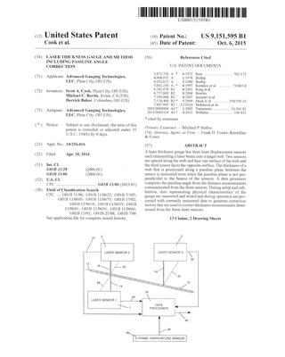
In April of 2014, Advanced Gauging Technologies L.L.C. (A.G.T.) filed a U.S. patent for the AGT800 Laser Thickness Gauge. The application was under review for more than a year. On October 6, 2015, we received notice that the examination was complete and we had been awarded U.S. Patent Number 9151595. We were approved for 13 of 14 submitted claims including our Passline Angle Compensation, C-frame temperature correction (ISOtemp™), and methods of computing laser beam collinearity and beam dynamics correction factors.
Approved Patent Claims
- A laser thickness gauge for detecting the thickness of a target web extending along a passline plane, the gauge comprising:
(a) a pair of laser displacement sensors each capable of transmitting a laser beam, spaced apart by an air gap distance A, and comprising a first laser sensor spaced from a first side of the passline plane and a second laser sensor spaced from a second, opposite side of the passline plane, the sensors being oriented to direct their laser beams parallel to and toward each other and intersecting a reference plane at 90 °, the first laser sensor having an output providing a signal representing the distance S1 between the first sensor and the web, the second laser sensor having an output providing a signal representing the distance S2 between the second sensor and the web;
(b) a third laser displacement sensor capable of transmitting a laser beam, spaced from the passline plane and located on the same side of the passline plane as the second laser sensor to have its laser beam spaced along the passline by a distance DS away from the laser beam of the second sensor, the third sensor oriented to direct its laser beam parallel to the laser beams of the pair of laser sensors and having an output providing a signal representing the distance A3 between the third sensor and the web; and
(c) a digital data processor including a storage memory for storing processing instructions and a value A representing the distance between the first laser sensor and the second laser sensor, the processor having an output and having inputs connected respectively to the outputs of the three laser sensors and receiving in real time a signal representing the distances S1, S2 and S3, the processor including a stored algorithm that computes in real time a measured thickness Tm of a web positioned along the passline plane in accordance with tan Θ =(S2-S3)/DS, passline angle Θ = arctan(tan Θ) and Tm = (A-S1-S2)cos Θ. wherein Θ is an angle between the reference plane and the passline plane and wherein the three laser sensors are mounted in an orientation so their parallel laser beams are oriented at an oblique angle to the passline plane.

- A laser thickness gauge in accordance with claim 1 wherein the processor has a stored value of an offset displacement Do of the first laser sensor from the second laser sensor and includes a stored algorithm that computes a colinearity offset correction factor Dc from Dc=Do(sin Θ) and algebraically sums the colinearity offset correction factor Dc beam dynamics correction factor Db with the measured thickness Tm to compute a corrected thickness.
- A laser thickness gauge in accordance with claim 2 wherein the processor has a stored value of a beam dynamics correction factor Db and includes a stored algorithm that also algebraically sums the beam dynamics correction factor Db with the measured thickness Tm to compute a corrected thickness.
- A laser thickness gauge in accordance with claim 3 and further comprising a support frame to which the laser sensors are mounted, a frame temperature sensor sensing the temperature t of the frame and having an output connected to the processor for computing the sensed temperature t to the processor, the processor has an experimentally obtained stored value of a temperature variation coefficient Ct and a stored temperature t0 at which the thickness gauge was calibrated, includes a stored algorithm for computing a temperature correction factor Dt from Dt=Ct(t-t0) and a stored algorithm that also algebraically sums the temperature correction factor Dt with the measured thickness Tm to compute a corrected thickness.
- A laser thickness gauge in accordance with claim 1 wherein the processor has a stored value of an offset displacement Do of the first laser sensor from the second laser sensor and includes a stored algorithm that computes a colinearity offset correction factor Dc from Dc=Do(sin Θ) and algebraically sums the colinearity offset correction factor Dc beam dynamics correction factor Db with the measured thickness Tm to compute a corrected thickness.

- A laser thickness gauge in accordance with claim 1 wherein the processor has a stored value of a beam dynamics correction factor Db and includes a stored algorithm that also algebraically sums the beam dynamics correction factor Db with the measured thickness Tm to compute a corrected thickness.
- A laser thickness gauge in accordance with claim 1 and further comprising a support frame to which the laser sensors are mounted, a frame temperature sensor sensing the temperature t of the frame and having an output connected to the processor for computing the sensed temperature t to the processor, the processor has an experimentally obtained stored value of a temperature variation coefficient Ct and a stored temperature t0 at which the thickness gauge was calibrated, includes a stored algorithm for computing a temperature correction factor Dt from Dt=Ct(t-t0) and a stored algorithm that also algebraically sums the temperature correction factor Dt with the measured thickness Tm to compute a corrected thickness.
- A method for measuring the thickness Ta of a target web extending along a passline plane using laser displacement sensors that have parallel laser beams incident upon the web at an oblique, non-perpendicular angle, the method comprising:
(a) measuring the distances S1 and S2 to transversely opposite locations on opposite sides of the web from a pair of the laser displacement sensors that are mounted on opposite sides of the web and spaced apart by an air gap distance A;
(b) measuring the distance S3 to the web from a third one of the laser displacement sensors that is longitudinally offset along the web by a distance DS from, and on the same side of the web as, one of the pair of laser displacement sensors;
(c) computing the oblique, non-perpendicular angle of incidence of the laser beams on the web from tan Θ = (S2- S3)/DS and Θ = arctan(tan Θ);
(d) computing in real time a measured thickness Tm from Tm=(A-S1-S2)cos Θ. - A method according to claim 8 and further comprising storing a value of an offset displacement Do of the first laser sensor from the second laser sensor, computing a colinearity offset correction factor Dc from Dc=Do(sin Θ) and algebraically summing the colinearity offset correction factor Dc with the thickness Tm measured by the three laser sensors to compute a corrected thickness measurement.
- A method according to claim 9 and further comprising storing a value of a beam dynamics correction factor Db and also algebraically summing the beam dynamics correction factor Db with the measured thickness Tm to compute a corrected thickness.
- A method according to claim 10 and further comprising:
(a) storing an experimentally obtained value of a temperature variation coefficient Ct;
(b) measuring a temperature to of a support frame to which the laser sensors are mounted during a calibration of the measuring steps and storing the temperature t0;
(c) periodically sensing and storing a temperature t of the support frame;
(d) computing a temperature correction factor Dt from Dt=Ct(t-t0); and also
(e) algebraically summing the temperature correction factor with the measured thickness Tm to compute a corrected thickness. - A method according to claim 8 and further comprising storing a value of a beam dynamics correction factor Db and also algebraically summing the beam dynamics correction factor Db with the measured thickness Tm to compute a corrected thickness.
- A method according to claim 8 and further comprising:
(a) storing an experimentally obtained value of a temperature variation coefficient Ct;
(b) measuring a temperature t0 of a support frame to which the laser sensors are mounted during a calibration of the measuring steps and storing the temperature to;
(c) periodically sensing and storing a temperature t of the support frame;
(d) computing a temperature correction factor Dt from Dt=Ct(t-t0); and also
(e) algebraically summing the temperature correction factor Dt with the measured thickness Tm to compute a corrected thickness.
A.G.T.’s focus has always been on its customers and throughout our history we’ve worked hard to develop new ideas for evolving thickness gauges to meet customer needs. Companies love the AGT800 Laser Thickness Gauge and that, along with confirmation of its innovative technology via a U.S. patent, is something we are very proud of.